|
Published by
Windtrap Limited 2005
Installation of Home Wind Turbine Kit
Please read after you have read the
instruction manual provided
INDEX
1. Introduction
2. Safety Information
3. Component Checklist
4. Turbine to Cable Connection
5. Cable to Regulator Connection
6. Regulator to Battery Connection
7. Battery to Inverter Connection
8. 913 Connection Kit Summary
9. Contact Information
1. Introduction
The 913 Connector Kit has been kitted together
to provide all the necessary components in order to complete
the installation of your wind turbine kit.
This Connector Kit works in conjunction with
the Home Wind Turbine Instruction Manual (you should already
have read this) and provides step by step picture instructions
to help walk you through the installation of your wind turbine
kit.
2. Safety Information
Read all instruction leaflets carefully before
installation.
Please ensure you do not allow the battery
terminal wires to connect together as this can cause an
electrical short and heat damage from arcing which can melt
steel! Ensure wind turbine is not spinning until all
connections are in place and the turbine firmly mounted. Wear
hand and eye protection while using the soldering iron which
will reach very high temperatures.
3. Component Checklist
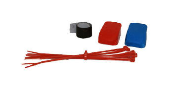
The 913 Connector Kit should include the
following items:
10 x Bag Ties to relieve pressure on
connectors in tower
1 x 10 strip self-amalg tape to
seal in the turbine connectors
1 x
Pair of battery connectors (snap-on battery terminal
connectors)
Please
note before connecting any kit
components together please cut approximately
1m off the 16m cable provided. This will be used to make battery
tails as shown in section 6.
4. Turbine to Cable Connection
The wind turbine should arrive with a cable
dangling out from the bottom of it. This cable is made up of a
red and black wire which is already attached to a cable
connector. The turbine cable needs to be connected to the 16m
length of cable supplied.
Please see below for step by step guidance:
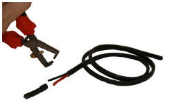
Using a
pair of wire strippers, strip the end of the 16m of cable
provided to expose both the red and black wire.
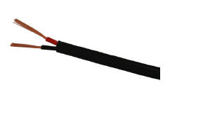
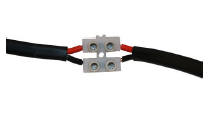
Next connect the red wire from the turbine
to the red wire of the cable and the black wire from the
turbine to the black wire of the cable. Attach these by
placing the wires in the cable connector, provided with the
turbine, and tighten using a small screwdriver.
Secure
the above turbine to cable connection using the
self-amalg tape provided. This will seal in the turbine
connector.
The turbine will
now be connected to the cable, ready to thread down through
the mounting poles.
Please note that the shorter
the cable distance, the more
efficient your whole turbine system will be. We recommend a
distance of approximately 10m from the turbine to the
regulator/battery/inverter. Note - It is possible to
increase this distance if heavier gauge wire is used.
5. Cable to Regulator Connection
Next thread the cable through the tower
sections and out of the base. Secure the cable in place using
the cable ties provided. The loose end of the 16m of cable is
now ready to be connected to the regulator. It is important
that the wind turbine is not rotating until ALL the electrical
connections are complete.
Using a pair of wire strippers, strip the
loose end of the 16m cable to expose the red and black wire.
The red and black wire also needs to be stripped to expose the
copper wire underneath. (Repeat step 4).
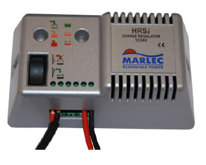
Attach the red cable wire to the +ve W.G
using a screwdriver.
Attach the black cable wire to the ve
W.G using a screwdriver.
6. Regulator to Battery Connection
The regulator is, as the name suggests, the
device that prevents the battery from becoming overcharged.
This is therefore an important part of the system as without
it the battery can become permanently damaged from
overcharging. To make this connection you will require the 1m
length of cable previously cut from the 16m cable provided.
Trim the 1m of cable back to produce both a red and a black
battery tail. You will then need to trim both ends of both
wires to expose the copper wire underneath. It is important to
not have loose threads sticking out. These could cause short
circuits.
Attach black battery tail to the ve
BATT port on the regulator.
Attach red battery tail to the +ve BATT
port on the regulator.
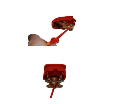
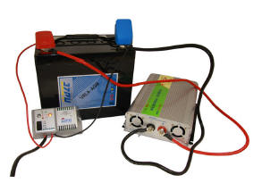
Connect battery tails
onto the battery snap-on terminals. Red tail to red terminal
and black tail to blue terminal as shown below.
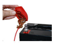
Connect the battery snap-on terminals onto
the battery. Red to red positive terminal and blue to black
negative terminal.
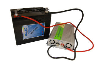
7. Battery to Inverter Connection
Connect the red inverter wire onto the red
DC output and the black inverter wire onto the black DC output
points on the inverter.
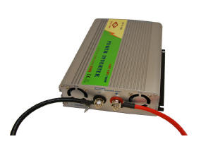
Then connect the red inverter wire around
the base of the red positive battery terminal and the black
inverter wire around the base of the black negative battery
terminal.
Once all components of the kit have been
connected together you are then able to either link your
system up to a lighting ring (please consult a qualified
electrician) or you can plug 12V appliances directly into the
socket on the inverter.
8. 913 Kit Connection Summary
Turbine to cable (Black to Black) (Red to
Red)
Cable to regulator
(Black to W.G ve)
(Red to W.G +ve)
Red battery tail to +ve regulator BATT
terminal
Black battery tail to ve regulator BATT
terminal
Red battery tail to red battery snap-on
terminal
Black battery tail to blue battery snap-on
terminal
For
a list of our client have a look at our About
Us section
Call:
+44(01234 841221
E-mail:
[email protected]
|


