|

Call:
+44(0)1234
841221
E-mail: [email protected]
Lg
Air Conditioning Fault Codes
A full list of LG
air conditioning fault codes by keyword
Need Lg Air
Conditioning spares parts?
We can ship Lg air
conditioning spare and parts including wall, cassette, floor, ducted and
multi air conditioning units’ parts. Please call or email us your Lg
unit model number and required part. We will then contact you with the
price, availability and shipping cost.
Contact:
Call:
+44(0)1234 841221
E-mail:
[email protected]
Fault
Codes:

|
Keyword
|
Response
|
|
00
|
Text
the 1, 2 or 3 digit fault code number only. I.e. If you see fault
code CH07 on your indoor unit or R/Controller, only type 7 or 07
in your text message.
|
|
01
|
Indoor
unit return air sensor fault. Disconnect sensor from PCB and
measure resistance. 8 kOhm at 30C and 13 kOhm at 20C if not
replace sensor
|
|
1
|
Indoor
unit return air sensor fault. Disconnect sensor from PCB and
measure resistance. 8 kOhm at 30C and 13 kOhm at 20C if not
replace sensor
|
|
02
|
Indoor
Pipe Sensor or Outdoor Sensor Assy fault, Open or Short.
Disconnect from PCB and measure resistance. Air sensor = 10 kOhm
at 25C, Pipe sensor = 5 kOhm at 25C. If not replace sensor.
|
|
2
|
Indoor
Pipe Sensor or Outdoor Sensor Assy fault, Open or Short.
Disconnect from PCB and measure resistance. Air sensor = 10 kOhm
at 25C, Pipe sensor = 5 kOhm at 25C. If not replace sensor.
|
|
03
|
Remote
controller comms error. Check wired correctly, if so check
dipswitch in RC. Set to Sg for 1 unit, or Gr for group then reset
power
|
|
3
|
Remote
controller comms error. Check wired correctly, if so check
dipswitch in RC. Set to Sg for 1 unit, or Gr for group then reset
power
|
|
04
|
RAC
Product = Heat Sink Sensor Error, Open/Short Cct or over 95C.
Commercial Product = Condensate pump float switch risen. Check
drain pan is empty, check pump is working OK. If no pump check
blue jumper plug is inserted in socket CN Float.
|
|
4
|
RAC
Product = Heat Sink Sensor Error, Open/Short Cct or over 95C.
Commercial Product = Condensate pump float switch risen. Check
drain pan is empty, check pump is working OK. If no pump check
blue jumper plug is inserted in socket CN Float.
|
|
05
|
Comms
Error, check your wiring, remove external pumps. Split/Multi -
check volts from terminal N to 3 = 0 - 65 Vdc, Multi V - 4 Vdc
terminals 3 and 4
|
|
5
|
Comms
Error, check your wiring, remove external pumps. Split/Multi -
check volts from terminal N to 3 = 0 - 65 Vdc, Multi V - 4 Vdc
terminals 3 and 4
|
|
06
|
Indoor
unit coil sensor fault. Disconnect from PCB measure resistance. 10
kOhm at 10C and 4 kOhm at 30C. if not replace sensor. Split = text
21
|
|
6
|
Indoor
unit coil sensor fault. Disconnect from PCB measure resistance. 10
kOhm at 10C and 4 kOhm at 30C. if not replace sensor. Split = text
21
|
|
07
|
Multi
Splits and Multi V = indoor unit is set to run in a different mode
from the master indoor unit. Set ALL indoor units to cooling or
ALL to heating to clear. Splits = Compressor Over Current (CT2),
also see Code 06.
|
|
7
|
Multi
Splits and Multi V = indoor unit is set to run in a different mode
from the master indoor unit. Set ALL indoor units to cooling or
ALL to heating to clear. Splits = Compressor Over Current (CT2),
also see Code 06.
|
| |
RAC
Indoor unit BLDC Fan problem. This is caused by the Indoor fan
being locked. Check fan motor is plugged in correctly,
Electrically & Mechanically sound.
|
|
08
|
Check
the fan motor turns freely, check the AC Voltage supplied to the
fan motor, this will vary from 120 V ac at low speed to 170V AC at
high speed. If no
|
| |
Voltage
is present the the PCB is faulty, if Voltage is present the fan
motor will be Faulty.
|
| |
RAC
Indoor unit BLDC Fan problem. This is caused by the Indoor fan
being locked. Check fan motor is plugged in correctly,
Electrically & Mechanically sound.
|
|
8
|
Check
the fan motor turns freely, check the AC Voltage supplied to the
fan motor, this will vary from 120 V ac at low speed to 170V AC at
high speed. If no
|
| |
Voltage
is present the the PCB is faulty, if Voltage is present the fan
motor will be Faulty.
|
|
09
|
Split
= Outdoor unit fan problem. Check Outdoor fan motor is plugged in,
Electrically & Mechanically sound, if not replace motor,
otherwise replace PCB. Multi V = Indoor unit EEPROM error -
Replace the indoor unit PCB, and then make sure to do Auto
addressing and input the address of central control.
|
|
9
|
Split
= Outdoor unit fan problem. Check Outdoor fan motor is plugged in,
Electrically & Mechanically sound, if not replace motor,
otherwise replace PCB. Multi V = Indoor unit EEPROM error -
Replace the indoor unit PCB, and then make sure to do Auto
addressing and input the address of central control.
|
|
10
|
RAC
Product: Compressor discharge sensor fault. Disconnect from PCB
measure resistance 237 kOhm at 20°C, 168 kOhm at 30C. Multi Fdx
& Multi V text 8
|
|
11
|
Multi
V indoor unit not connected to an outdoor unit. Check comms wiring
is correct, and check initialisation has been carried out
correctly
|
|
12
|
RAC
Product = EEPROM Sum Check Error, text 60 for help.
|
|
13
|
RAC
Product = PSC (Reactor) Error, text 27 for help.
|
|
14
|
RAC
Product = Compressor Phase Current Error
|
|
15
|
no
such fault code Text 1, 2 or 3 digit fault code number only. If
you see fault code CH07 only type 7 in your text message
|
|
16
|
no
such fault code Text 1, 2 or 3 digit fault code number only. If
you see fault code CH07 only type 7 in your text message
|
|
17
|
no
such fault code Text 1, 2 or 3 digit fault code number only. If
you see fault code CH07 only type 7 in your text message
|
|
18
|
no
such fault code Text 1, 2 or 3 digit fault code number only. If
you see fault code CH07 only type 7 in your text message
|
|
19
|
no
such fault code Text 1, 2 or 3 digit fault code number only. If
you see fault code CH07 only type 7 in your text message
|
|
20
|
no
such fault code Text 1, 2 or 3 digit fault code number only. If
you see fault code CH07 only type 7 in your text message
|
|
21
|
Inverter
compressor run current high. Check compressor windings all equal 1
to 4 Ohms, Check to earth 50 MOhm minimum, check run current
|
|
22
|
Inverter
compressor run current high. Check compressor windings all equal 1
to 4 Ohms . Check to earth 50 MOhm minimum, check run current
|
|
23
|
Inverter
dc voltage low. Check dc voltage of capacitors 300 Vdc for 1Ph and
600 Vdc for 3Ph. If OK change outdoor inverter PCB
|
|
24
|
Splits
and Multi Splits = High or low pressure trip. Low at 1 bar High at
35 bar check pressures. Multi V = High pressure trip.
|
|
25
|
Check
power supply voltage to the outdoor unit is correct (1ph ?220 Vac
±10% or 3ph ?380 Vac ±10%). If OK, check fuses, if fuses are OK
replace outdoor main PCB
|
|
26
|
Inverter
compressor seized. Check compressor windings all equal resistance
1 to 4 Ohms, check to earth 50 MOhm minimum, check run current and
Inverter outputs
|
|
27
|
Inverter
current irregularity. Check inverter PCB, check reactor
connections and its resistance is less than 1 ohm.
|
|
28
|
Inverter
dc voltage too high. Check dc voltage of capacitors 300 Vdc for
1Ph and 600 Vdc for 3Ph. If OK change outdoor inverter PCB
|
|
29
|
no
such fault code Text 1, 2 or 3 digit fault code number only. If
you see fault code CH07 only type 7 in your text message
|
|
30
|
no
such fault code Text 1, 2 or 3 digit fault code number only. If
you see fault code CH07 only type 7 in your text message
|
|
31
|
no
such fault code Text 1, 2 or 3 digit fault code number only. If
you see fault code CH07 only type 7 in your text message
|
|
32
|
Inverter
compressor discharge temperature too high. If over 105°C, check
refrigerant charge
|
|
33
|
Excessive
rise of standard compressor discharge temperature. If over 105°C
check refrigerant charge
|
|
34
|
Excessive
high pressure rise, over 35 bar at HP sensor. Check pressures,
check coils, and filters are clean check for OFN in system
pipework
|
|
35
|
Excessive
low pressure drop under 1 Bar at LP sensor. Check pressures, and
check service valves open
|
|
36
|
no
such fault code Text 1, 2 or 3 digit fault code number only. If
you see fault code CH07 only type 7 in your text message
|
|
37
|
no
such fault code Text 1, 2 or 3 digit fault code number only. If
you see fault code CH07 only type 7 in your text message
|
|
38
|
no
such fault code Text 1, 2 or 3 digit fault code number only. If
you see fault code CH07 only type 7 in your text message
|
|
39
|
no
such fault code Text 1, 2 or 3 digit fault code number only. If
you see fault code CH07 only type 7 in your text message
|
|
40
|
Inverter
ac current abnormal. Check compressor windings all equal
resistance 1 to 4 Ohms, check to earth 50 MOhm minimum, check run
current and inverter outputs
|
|
41
|
Inverter
compressor discharge sensor fault. Disconnect from PCB measure
resistance 237 kOhm at 20°C and 168 kOhm at 30°C.
|
|
42
|
Low
pressure sensor fault. Check dc voltage between white and black
cable on plug. Multi V: 1 Vdc = 4 bar up to 5 Vdc = 32 bar
|
|
43
|
High
pressure sensor fault. Check dc voltage between white and black
cable on plug. Multi V: 1 Vdc = 8 bar up to 2.5 Vdc = 37 bar
|
|
44
|
Outdoor
unit air sensor fault. Disconnect from PCB and measure resistance.
8 kOhm at 30C and 13 kOhm at 20C. If OK replace PCB, if not
replace sensor
|
|
45
|
Outdoor
unit coil sensor fault. Disconnect from PCB measure resistance. 10
kOhm at 10°C and 4 kOhm at 30°C. If OK replace PCB, if not
replace sensor
|
|
46
|
Outdoor
unit suction sensor fault. Disconnect from PCB and measure
resistance. 10 kOhm at 10°C and 4 kOhm at 30°C. If OK replace
PCB, if not replace sensor
|
|
47
|
Compressor
discharge sensor fault. Disconnect from PCB measure resistance.
237 kOhm at 20°C and 168 kOhm at 30°C. If OK replace PCB, if not
replace sensor
|
|
48
|
Split/Multi
Split = Outdoor unit discharge and air sensor both unplugged.
Multi V = Outdoor unit coil sensor. Text 45 for diagnostics
|
|
49
|
Check
power supply voltage to the outdoor unit is correct (1ph ?220 Vac
±10% or 3ph ?380 Vac ±10%). If OK check fuses, if fuses OK,
replace outdoor main PCB
|
|
50
|
no
such fault code Text 1, 2 or 3 digit fault code number only. If
you see fault code CH07 only type 7 in your text message
|
|
51
|
Unit
mismatch. Check model number of units do not exceed maximum. Multi
V - also check Sub outdoor unit dipswitch settings
|
|
52
|
Communication
error between inverter PCB and main outdoor unit PCB. Check wiring
fuses and LEDs . If OK either inverter or main PCB defective
|
|
53
|
Comms
error indoor to outdoor unit. Check your wiring . Split and Multi
- check voltage from terminal N to 3 = 0 - 65 Vdc, Multi V - 4 Vdc
terminals 3 and 4
|
|
54
|
Reverse
or open phase. Check all 3 phases are present and correct. If
correct voltage appears at all three phases, swap any two to cure
the fault
|
|
55
|
no
such fault code Text 1, 2 or 3 digit fault code number only. If
you see fault code CH07 only type 7 in your text message
|
|
56
|
no
such fault code Text 1, 2 or 3 digit fault code number only. If
you see fault code CH07 only type 7 in your text message
|
|
57
|
Comms
error between outdoor main PCB and inverter PCB. Check wiring
fuses and LEDs are lit. If OK either inverter or main PCB
defective
|
|
58
|
no
such fault code Text 1, 2 or 3 digit fault code number only. If
you see fault code CH07 only type 7 in your text message
|
|
59
|
no
such fault code Text 1, 2 or 3 digit fault code number only. If
you see fault code CH07 only type 7 in your text message
|
|
60
|
Outdoor
unit PCB EEPROM failure, try removing EEPROM and refitting if
removable (possible contact fault), otherwise replace PCB if the
EEPROM is non-removable.
|
|
61
|
Condenser
coil over 65°C. Check coil and filters are clean and free from
debris, and airflow is OK. Check system pressures for
non-condesables
|
|
62
|
Inverter
over 85°C. Check air flow across heat sink, check inverter tight
to heatsink use thermal paste. Multi V - check inverter cooling
fan
|
|
63
|
Multi
F(DX) - "Cond. Pipe Sensor Temp. Low" (opposite to Error
Code 61). Check Temperature/Resistance reading and replace sensor
if found to be faulty. If sensor okay, check for cause of low
temperature and rectify.
|
|
64
|
no
such fault code Text 1, 2 or 3 digit fault code number only. If
you see fault code CH07 only type 7 in your text message
|
|
65
|
Outdoor
unit inverter fin temperature sensor fault. Disconnect from PCB
measure resistance. 8 kOhm at 30°C and 13 kOhm at 20°C
|
|
67
|
Outdoor
Fan Motor siezed, or rotation sensing circuit failure. Check motor
for mechanical and/or electrical failure, if okay replace pcb.
|
|
100
|
Excessive
discharge temperature rise 105°C Sub condenser 1 standard
compressor. Check refrigerant
|
|
101
|
Excessive
discharge temperature rise 105°C Sub condenser 1 standard
compressor. Check refrigerant
|
|
102
|
Excessive
discharge temperature rise 105°C Sub condenser 2 standard
compressor. Check refrigerant
|
|
103
|
Excessive
discharge temperature rise 105°C Sub condenser 2 standard
compressor. Check refrigerant
|
|
104
|
Communication
error between Main and Sub outdoor units. Check comms wiring and
power to all outdoor units
|
|
105
|
Communication
error between outdoor main PCB and fan PCB. Check plug connections
and LEDs. If OK, replace either main or fan PCB
|
|
106
|
Outdoor
unit fan motor high current. Check fans rotate freely, and are
connected correctly
|
|
107
|
Outdoor
unit low voltage to fan PCB. Check 300 Vdc supply, check fuses and
plug connections. If OK, replace fan PCB
|
|
108
|
Communication
error between outdoor main PCB, and fan PCB. Check plug
connections and LEDs. If OK replace either main or fan PCB
|
|
109
|
Sub
1 excessive rise of high pressure. Check pressures, check for non
condensables, check heat exchanger coil is free from debris
|
|
110
|
Sub
1 reverse or open phase. Check all 3 phases are present and
correct. If correct voltage appears at all three phases, swap any
two to cure the fault
|
|
111
|
Communication
error between Main and Sub outdoor units. Check comms wiring and
power to all outdoor units
|
|
113
|
Main
outdoor unit liquid pipe sensor fault. Disconnect from PCB and
measure resistance. 10 kOhm at 10°C and 4 kOhm at 30°C
|
|
114
|
Main
outdoor unit Subcool inlet sensor fault. Disconnect from PCB and
measure resistance. 10 kOhm at 10°C and 4 kOhm at 30°C
|
|
115
|
Main
outdoor unit Subcool outlet sensor fault. Disconnect from PCB and
measure resistance. 10 kOhm at 10°C and 4 kOhm at 30°C
|
|
116
|
Sub
1 high pressure sensor fault. Check dc voltage between white and
black cable on plug. Multi V: 1 Vdc = 8 bar up to 2.5 Vdc = 37 bar
|
|
117
|
Sub
1 low pressure sensor fault. Check dc voltage between white and
black cable on plug. Multi V: 1 Vdc = 4 bar up to 5 Vdc = 32 bar
|
|
118
|
Sub
1 outdoor unit air sensor fault. Disconnect from PCB and measure
resistance. 8 kOhm at 30°C and 13 kOhm at 20°C. If OK replace
PCB, if not replace sensor
|
|
120
|
Sub
1 outdoor unit suction sensor fault. Disconnect from PCB and
measure resistance. 10 kOhm at 10°C and 4 kOhm at 30°C. if not
replace sensor
|
|
121
|
Sub
1 compressor 1 discharge sensor fault. Disconnect from PCB measure
resistance 237 kOhm at 20°C and 168 kOhm at 30°C. if not replace
sensor
|
|
122
|
Sub
1 compressor 2 discharge sensor fault. Disconnect from PCB measure
resistance 237 kOhm at 20°C and 168 kOhm at 30°C. if not replace
sensor
|
|
123
|
Sub
1 outdoor unit coil sensor A fault. Disconnect from PCB measure
resistance. 10 kOhm at 10°C and 4 kOhm at 30°C. If OK replace
PCB, if not replace sensor
|
|
124
|
Sub
1 outdoor unit coil sensor B fault. Disconnect from PCB measure
resistance. 10 kOhm at 10°C and 4 kOhm at 30°C. If OK replace
PCB, if not replace sensor
|
|
125
|
Sub
1 outdoor unit liquid pipe sensor fault. Disconnect from PCB and
measure resistance. 10 kOhm at 10°C and 4 kOhm at 30°C
|
|
126
|
Sub
1 outdoor unit Subcool inlet sensor fault. Disconnect from PCB and
measure resistance. 10 kOhm at 10°C and 4 kOhm at 30°C
|
|
127
|
Sub
1 outdoor unit Subcool outlet sensor fault. Disconnect from PCB
and measure resistance. 10 kOhm at 10°C and 4 kOhm at 30°C
|
|
128
|
Sub
2 high pressure sensor fault. Check dc voltage between white and
black cable on plug. Multi V: 1 Vdc = 8 bar up to 2.5 Vdc = 37 bar
|
|
129
|
Sub
2 low pressure sensor fault. Check dc voltage between white and
black cable on plug. Multi V: 1 Vdc = 4 bar up to 5 Vdc = 32 bar
|
|
130
|
Sub
2 outdoor unit air sensor fault. Disconnect from PCB and measure
resistance. 8 kOhm at 30°C and 13 kOhm at 20°C. If OK replace
PCB, if not replace sensor
|
|
132
|
Sub
2 outdoor unit suction sensor fault. Disconnect from PCB and
measure resistance. 10 kOhm at 10°C and 4 kOhm at 30°C.if not
replace sensor
|
|
133
|
Sub
2 compressor 1 discharge sensor fault. Disconnect from PCB measure
resistance 237 kOhm at 20°C and 168kOhm at 30°C. if not replace
sensor
|
|
134
|
Sub
2 compressor 2 discharge sensor fault. Disconnect from PCB measure
resistance 237 kOhm at 20°C and 168kOhm at 30°C.if not replace
sensor
|
|
135
|
Sub
2 outdoor unit coil sensor A fault. Disconnect from PCB measure
resistance. 10 kOhm at 10°C and 4 kOhm at 30°C. If OK replace
PCB, if not replace sensor
|
|
136
|
Sub
2 outdoor unit coil sensor B fault. Disconnect from PCB measure
resistance. 10 kOhm at 10°C and 4 kOhm at 30°C. If OK replace
PCB, if not replace sensor
|
|
137
|
Sub
2 outdoor unit liquid pipe sensor fault. Disconnect from PCB and
measure resistance. 10 kOhm at 10°C and 4 kOhm at 30°C
|
|
138
|
Sub
2 outdoor unit Subcool inlet sensor fault. Disconnect from PCB and
measure resistance. 10 kOhm at 10°C and 4 kOhm at 30°C
|
|
139
|
Sub
2 outdoor unit Subcool outlet sensor fault. Disconnect from PCB
and measure resistance. 10 kOhm at 10°C and 4 kOhm at 30°C
|
|
140
|
Sub
2 excessive rise of high pressure. Check pressures, check for non
condensables, check heat exchanger coil is free from debris
|
|
141
|
Sub
2 reverse or open phase. Check all 3 phases are present and
correct. If correct voltage appears at all three phases, swap any
two to cure the fault
|
|
142
|
Communication
error between Main and Sub outdoor units. Check comms wiring and
power to all outdoor units
|
|
143
|
Sub
1 excessive rise of high pressure. Check pressures, check for non
condensables, check heat exchanger coil is free from debris
|
|
144
|
Sub
1 excessive drop of low pressure. Check pressures, check for non
condensables, check heat exchanger coil is free from debris
|
|
145
|
Sub
2 excessive rise of high pressure. Check pressures, check for non
condensables, check heat exchanger coil is free from debris
|
|
146
|
Sub
2 excessive drop of low pressure. Check pressures, check for non
condensables, check heat exchanger coil is free from debris
|
|
147
|
Sub
1 check power supply voltage to the outdoor unit is correct (1ph
220 Vac ±10% or 3ph 380 Vac ±10%).check fuses, if fuses OK
replace outdoor main PCB
|
|
148
|
Sub
1 check power supply voltage to the outdoor unit is correct (1ph
220 Vac ±10% or 3ph 380 Vac ±10%). check fuses, if fuses OK
replace outdoor main PCB
|
|
149
|
Sub
2 check power supply voltage to the outdoor unit is correct (1ph
220 Vac ±10% or 3ph 380 Vac ±10%). check fuses, if fuses OK
replace outdoor main PCB
|
|
150
|
Sub
2 check power supply voltage to the outdoor unit is correct (1ph
220 Vac ±10% or 3ph 380 Vac ±10%). check fuses, if fuses OK
replace outdoor main PCB
|
|
151
|
Faulty
4 way valve. Check solenoid coil and output from PCB. If OK,
mechanical failure.
|
|
152
|
Excessive
discharge temperature rise 105°C Sub condenser 2 standard
compressor. Check refrigerant
|
|
153
|
Excessive
discharge temperature rise 105°C Sub condenser 2 standard
compressor. Check refrigerant
|
|
154
|
Sub
3 excessive rise of high pressure. Check pressures, check for non
condensables, check heat exchanger coil is free from debris
|
|
155
|
Sub
3 reverse or open phase. Check all 3 phases are present and
correct. If correct voltage appears at all three phases, swap any
two to cure the fault
|
|
156
|
Communication
error between Main and Sub outdoor units. Check comms wiring and
power to all outdoor units
|
|
157
|
Sub
3 high pressure sensor fault. Check dc voltage between white and
black cable on plug. Multi V: 1 Vdc = 8 bar up to 2.5 Vdc = 37 bar
|
|
158
|
Sub
3 low pressure sensor fault. Check dc voltage between white and
black cable on plug. Multi V: 1 Vdc = 4 bar up to 5 Vdc = 32 bar
|
|
159
|
Sub
3 outdoor unit air sensor fault. Disconnect from PCB and measure
resistance. 8 kOhm at 30°C and 13 kOhm at 20°C. If OK replace
PCB, if not replace sensor
|
|
161
|
Sub
3 outdoor unit suction sensor fault. Disconnect from PCB and
measure resistance. 10 kOhm at 10°C and 4 kOhm at 30°C. if not
replace sensor
|
|
162
|
Sub
3 compressor 1 discharge sensor fault. Disconnect from PCB measure
resistance 237 kOhm at 20°C and 168 kOhm at 30°C. if not replace
sensor
|
|
163
|
Sub
3 compressor 2 discharge sensor fault. Disconnect from PCB measure
resistance 237 kOhm at 20°C and 168 kOhm at 30°C.if not replace
sensor
|
|
164
|
Sub
3 outdoor unit coil sensor A fault. Disconnect from PCB measure
resistance. 10 kOhm at 10°C and 4 kOhm at 30°C. If OK replace
PCB, if not replace sensor
|
|
165
|
Sub
3 outdoor unit coil sensor B fault. Disconnect from PCB measure
resistance. 10 kOhm at 10°C and 4 kOhm at 30°C. If OK replace
PCB, if not replace sensor
|
|
166
|
Sub
3 outdoor unit liquid pipe sensor fault. Disconnect from PCB and
measure resistance. 10 kOhm at 10°C and 4 kOhm at 30°C
|
|
167
|
Sub
3 outdoor unit Subcool inlet sensor fault. Disconnect from PCB and
measure resistance. 10 kOhm at 10°C and 4 kOhm at 30°C
|
|
168
|
Sub
3 outdoor unit Subcool outlet sensor fault. Disconnect from PCB
and measure resistance. 10 kOhm at 10°C and 4 kOhm at 30°C
|
|
169
|
Sub
3 excessive rise of high pressure. Check pressures, check for non
condensables, check heat exchanger coil is free from debris
|
|
170
|
Sub
3 excessive drop of low pressure. Check pressures, check for non
condensables, check heat exchanger coil is free from debris
|
|
171
|
Sub
3 check power supply voltage to the outdoor unit is correct (1ph
220 Vac ±10% or 3ph 380 Vac ±10%). check fuses, if fuses OK
replace outdoor main PCB
|
|
172
|
Sub
3 check power supply voltage to the outdoor unit is correct (1ph
220 Vac ±10% or 3ph 380 Vac ±10%). check fuses, if fuses OK
replace outdoor main PCB
|
|
173
|
Main
outdoor unit standard compressor not starting. Check output from
main PCB, check contactor, and check wiring connections. If OK
compressor faulty
|
|
174
|
Sub
1 standard compressor 1 not starting. Check output from main PCB,
check contactor, and check wiring connections. If OK compressor
faulty
|
|
175
|
Sub
1 standard compressor 2 not starting. Check output from main PCB,
check contactor, and check wiring connections. If OK compressor
faulty
|
|
176
|
Sub
2 standard compressor 1 not starting. Check output from main PCB,
check contactor, and check wiring connections. If OK compressor
faulty
|
|
177
|
Sub
2 standard compressor 2 not starting. Check output from main PCB,
check contactor, and check wiring connections. If OK compressor
faulty
|
|
204
|
Comms
Error between Outdoor Unit and HR Box No1. 1. Defective connection
in HR unit power supply and transmission connection 2. Wrong
setting of the HR unit Rotary switch and Dip switch 3. Defective
HR unit PCB
|
|
208
|
Comms
Error between Outdoor Unit and HR Box No2. 1. Defective connection
in HR unit power supply and transmission connection 2. Wrong
setting of the HR unit Rotary switch and Dip switch 3. Defective
HR unit PCB
|
|
212
|
Comms
Error between Outdoor Unit and HR Box No3. 1. Defective connection
in HR unit power supply and transmission connection 2. Wrong
setting of the HR unit Rotary switch and Dip switch 3. Defective
HR unit PCB
|
|
240
|
Central
controller wiring error. Check all comms wiring, including between
controller and CNU, and IP addresses. If OK possible defective CNU
|
|
241
|
Central
controller data sending error. Either defective CNU or Central
controller initialisation failure
|
|
242
|
Central
controller data receiving error. Either defective CNU or Central
controller initialisation failure
|
|
243
|
Central
controller. Comms cable too long or picking up external electrical
noise. If OK, mismatching of controllers, or defective CNU
|
|
244
|
Central
controller data receiving time out. Either defective CNU or
Central controller initialisation failure
|
|
245
|
Central
controller data sending time out. Either defective CNU or Central
controller initialisation failure
|
|
246
|
Central
controller data receiving time out. Either defective CNU or
Central controller initialisation failure
|
|
250
|
Central
controller data receiving error. Either comms cable picking up
external electrical noise, or defective CNU
|
|
251
|
Central
controller receiving no data. Either comms cable picking up
external electrical noise, or defective CNU
|
|
252
|
Central
controller incorrect address error. Check addresses match, if OK
either comms cable picking up external electrical noise, or
defective CNU
|
|
253
|
Central
Controller Disconnection Error, No response from Air Conditioner.
Check wiring, if OK either comms cable picking up external
electrical noise, defective CNU, or Interface.
|
|
C1
|
Indoor
unit return air sensor fault, Open or Short. Disconnect sensor
from PCB and measure resistance. 8 kOhm at 30C and 13 kOhm at 20C
if not replace sensor
|
|
C2
|
Indoor
Pipe Sensor or Outdoor Sensor Assy fault, Open or Short.
Disconnect from PCB and measure resistance. Air sensor = 10 kOhm
at 25C, Pipe sensor = 5 kOhm at 25C. If not replace sensor.
|
|
C4
|
RAC
Product = Heat Sink Sensor Error, Open/Short Cct or over 95C.
Commercial Product = Condensate pump float switch risen. Check
drain pan is empty, check pump is working OK. If no pump check
blue jumper plug is inserted in socket CN Float.
|
|
C5
|
Comms
Error, check your wiring, remove external pumps. Split/Multi -
check volts from terminal N to 3 = 0 - 65 Vdc, Multi V - 4 Vdc
terminals 3 and 4
|
|
C6
|
Inverter
compressor run current high. Check compressor windings all equal 1
to 4 Ohms, Check to earth 50 MOhm minimum, check run current
|
|
C7
|
Splits
= Compressor Over Current (CT2), also see Code 06.
|
| |
RAC
Indoor unit BLDC Fan problem. This is caused by the Indoor fan
being locked. Check fan motor is plugged in correctly,
Electrically & Mechanically sound.
|
|
C8
|
Check
the fan motor turns freely, check the AC Voltage supplied to the
fan motor, this will vary from 120 V ac at low speed to 170V AC at
high speed. If no
|
| |
Voltage
is present the the PCB is faulty, if Voltage is present the fan
motor will be Faulty.
|
|
C9
|
Outdoor
unit fan problem. Check Outdoor fan motor is plugged in,
Electrically & Mechanically sound, if not replace motor,
otherwise replace PCB.
|
|
CA
|
Compressor
discharge sensor fault. Disconnect from PCB measure resistance 237
kOhm at 20°C, 168 kOhm at 30C.
|
|
CC
|
RAC
Product = EEPROM Sum Check Error, text 60 for help.
|
|
Cd
|
RAC
Product = PSC (Reactor) Error, text 27 for help.
|
|
CE
|
RAC
Product = Compressor Phase Current Error
|
|
CH00
|
Text
the 1, 2 or 3 digit fault code number only. I.e. If you see fault
code CH07 on your indoor unit or R/Controller, only type 7 or 07
in your text message.
|
|
CH01
|
Indoor
unit return air sensor fault. Disconnect sensor from PCB and
measure resistance. 8 kOhm at 30C and 13 kOhm at 20C if not
replace sensor
|
|
CH02
|
Indoor
Pipe Sensor or Outdoor Sensor Assy fault, Open or Short.
Disconnect from PCB and measure resistance. Air sensor = 10 kOhm
at 25C, Pipe sensor = 5 kOhm at 25C. If not replace sensor.
|
|
CH03
|
Remote
controller comms error. Check wired correctly, if so check
dipswitch in RC. Set to Sg for 1 unit, or Gr for group then reset
power
|
|
CH04
|
RAC
Product = Heat Sink Sensor Error, Open/Short Cct or over 95C.
Commercial Product = Condensate pump float switch risen. Check
drain pan is empty, check pump is working OK. If no pump check
blue jumper plug is inserted in socket CN Float.
|
|
CH05
|
Comms
Error, check your wiring, remove external pumps. Split/Multi -
check volts from terminal N to 3 = 0 - 65 Vdc, Multi V - 4 Vdc
terminals 3 and 4
|
|
CH06
|
Indoor
unit coil sensor fault. Disconnect from PCB measure resistance. 10
kOhm at 10C and 4 kOhm at 30C. if not replace sensor. Split = text
21
|
|
CH07
|
Multi
Splits and Multi V = indoor unit is set to run in a different mode
from the master indoor unit. Set ALL indoor units to cooling or
ALL to heating to clear. Splits = Compressor Over Current (CT2),
also see Code 06.
|
| |
RAC
Indoor unit BLDC Fan problem. This is caused by the Indoor fan
being locked. Check fan motor is plugged in correctly,
Electrically & Mechanically sound.
|
|
CH08
|
Check
the fan motor turns freely, check the AC Voltage supplied to the
fan motor, this will vary from 120 V ac at low speed to 170V AC at
high speed. If no
|
| |
Voltage
is present the the PCB is faulty, if Voltage is present the fan
motor will be Faulty.
|
|
CH09
|
Split
= Outdoor unit fan problem. Check Outdoor fan motor is plugged in,
Electrically & Mechanically sound, if not replace motor,
otherwise replace PCB. Multi V = indoor PCB failure. Replace PCB
|
|
CH10
|
RAC
Product: Compressor discharge sensor fault. Disconnect from PCB
measure resistance 237 kOhm at 20°C, 168 kOhm at 30C. Multi Fdx
& Multi V text 8
|
|
CH11
|
Multi
V indoor unit not connected to an outdoor unit. Check comms wiring
is correct, and check initialisation has been carried out
correctly
|
|
CH12
|
no
such fault code Text 1, 2 or 3 digit fault code number only. If
you see fault code CH07 only type 7 in your text message
|
|
CH13
|
no
such fault code Text 1, 2 or 3 digit fault code number only. If
you see fault code CH07 only type 7 in your text message
|
|
CH14
|
no
such fault code Text 1, 2 or 3 digit fault code number only. If
you see fault code CH07 only type 7 in your text message
|
|
CH15
|
no
such fault code Text 1, 2 or 3 digit fault code number only. If
you see fault code CH07 only type 7 in your text message
|
|
CH16
|
no
such fault code Text 1, 2 or 3 digit fault code number only. If
you see fault code CH07 only type 7 in your text message
|
|
CH17
|
no
such fault code Text 1, 2 or 3 digit fault code number only. If
you see fault code CH07 only type 7 in your text message
|
|
CH18
|
no
such fault code Text 1, 2 or 3 digit fault code number only. If
you see fault code CH07 only type 7 in your text message
|
|
CH19
|
no
such fault code Text 1, 2 or 3 digit fault code number only. If
you see fault code CH07 only type 7 in your text message
|
|
CH20
|
no
such fault code Text 1, 2 or 3 digit fault code number only. If
you see fault code CH07 only type 7 in your text message
|
|
CH21
|
Inverter
compressor run current high. Check compressor windings all equal 1
to 4 OhmsCheck to earth 50 MOhm minimum, check run current
|
|
CH22
|
Inverter
compressor run current high. Check compressor windings all equal 1
to 4 Ohms . Check to earth 50 MOhm minimum, check run current
|
|
CH23
|
Inverter
dc voltage low. Check dc voltage of capacitors 300 Vdc for 1Ph and
600 Vdc for 3Ph. If OK change outdoor inverter PCB
|
|
CH24
|
Splits
and Multi Splits = High or low pressure trip. Low at 1 bar High at
35 bar check pressures. Multi V = High pressure trip.
|
|
CH25
|
Check
power supply voltage to the outdoor unit is correct (1ph ?220 Vac
±10% or 3ph ?380 Vac ±10%). If OK, check fuses, if fuses are OK
replace outdoor main PCB
|
|
CH26
|
Inverter
compressor seized. Check compressor windings all equal resistance
1 to 4 Ohms, check to earth 50 MOhm minimum, check run current and
Inverter outputs
|
|
CH27
|
Inverter
current irregularity. Check inverter PCB and reactor
|
|
CH28
|
Inverter
dc voltage too high. Check dc voltage of capacitors 300 Vdc for
1Ph and 600 Vdc for 3Ph. If OK change outdoor inverter PCB
|
|
CH29
|
no
such fault code Text 1, 2 or 3 digit fault code number only. If
you see fault code CH07 only type 7 in your text message
|
|
CH30
|
no
such fault code Text 1, 2 or 3 digit fault code number only. If
you see fault code CH07 only type 7 in your text message
|
|
CH31
|
no
such fault code Text 1, 2 or 3 digit fault code number only. If
you see fault code CH07 only type 7 in your text message
|
|
CH32
|
Inverter
compressor discharge temperature too high. If over 105°C, check
refrigerant charge
|
|
CH33
|
Excessive
rise of standard compressor discharge temperature. If over 105°C
check refrigerant charge
|
|
CH34
|
Excessive
high pressure rise, over 35 bar at HP sensor. Check pressures,
check coils, and filters are clean check for OFN in system
pipework
|
|
CH35
|
Excessive
low pressure drop under 1 Bar at LP sensor. Check pressures, and
check service valves open
|
|
CH36
|
no
such fault code Text 1, 2 or 3 digit fault code number only. If
you see fault code CH07 only type 7 in your text message
|
|
CH37
|
no
such fault code Text 1, 2 or 3 digit fault code number only. If
you see fault code CH07 only type 7 in your text message
|
|
CH38
|
no
such fault code Text 1, 2 or 3 digit fault code number only. If
you see fault code CH07 only type 7 in your text message
|
|
CH39
|
no
such fault code Text 1, 2 or 3 digit fault code number only. If
you see fault code CH07 only type 7 in your text message
|
|
CH40
|
Inverter
ac current abnormal. Check compressor windings all equal
resistance 1 to 4 Ohms, check to earth 50 MOhm minimum, check run
current and inverter outputs
|
|
CH41
|
Inverter
compressor discharge sensor fault. Disconnect from PCB measure
resistance 237 kOhm at 20C and 168 kOhm at 30C.
|
|
CH42
|
Low
pressure sensor fault. Check dc voltage between white and black
cable on plug. Multi V: 1 Vdc = 4 bar up to 5 Vdc = 32 bar
|
|
CH43
|
High
pressure sensor fault. Check dc voltage between white and black
cable on plug. Multi V: 1 Vdc = 8 bar up to 2.5 Vdc = 37 bar
|
|
CH44
|
Outdoor
unit air sensor fault. Disconnect from PCB and measure resistance.
8 kOhm at 30°C and 13 kOhm at 20°C. If OK replace PCB, if not
replace sensor
|
|
CH45
|
Outdoor
unit coil sensor fault. Disconnect from PCB measure resistance. 10
kOhm at 10°C and 4 kOhm at 30°C. If OK replace PCB, if not
replace sensor
|
|
CH46
|
Outdoor
unit suction sensor fault. Disconnect from PCB and measure
resistance. 10 kOhm at 10°C and 4 kOhm at 30°C. If OK replace
PCB, if not replace sensor
|
|
CH47
|
Compressor
discharge sensor fault. Disconnect from PCB measure resistance.
237 kOhm at 20°C and 168 kOhm at 30°C. If OK replace PCB, if not
replace sensor
|
|
CH48
|
Split/Multi
Split = Outdoor unit discharge and air sensor both unplugged.
Multi V = Outdoor unit coil sensor. Text 45 for diagnostics
|
|
CH49
|
Check
power supply voltage to the outdoor unit is correct (1ph ?220 Vac
±10% or 3ph ?380 Vac ±10%). If OK check fuses, if fuses OK,
replace outdoor main PCB
|
|
CH50
|
no
such fault code Text 1, 2 or 3 digit fault code number only. If
you see fault code CH07 only type 7 in your text message
|
|
CH51
|
Unit
mismatch. Check model number of units do not exceed maximum. Multi
V - also check Sub outdoor unit dipswitch settings
|
|
CH52
|
Communication
error between inverter PCB and main outdoor unit PCB. Check wiring
fuses and LEDs . If OK either inverter or main PCB defective
|
|
CH53
|
Comms
error indoor to outdoor unit. Check your wiring . Split and Multi
- check voltage from terminal N to 3 = 0 - 65 Vdc, Multi V - 4 Vdc
terminals 3 and 4
|
|
CH54
|
Reverse
or open phase. Check all 3 phases are present and correct. If
correct voltage appears at all three phases, swap any two to cure
the fault
|
|
CH55
|
no
such fault code Text 1, 2 or 3 digit fault code number only. If
you see fault code CH07 only type 7 in your text message
|
|
CH56
|
no
such fault code Text 1, 2 or 3 digit fault code number only. If
you see fault code CH07 only type 7 in your text message
|
|
CH57
|
Comms
error between outdoor main PCB and inverter PCB. Check wiring
fuses and LEDs are lit. If OK either inverter or main PCB
defective
|
|
CH58
|
no
such fault code Text 1, 2 or 3 digit fault code number only. If
you see fault code CH07 only type 7 in your text message
|
|
CH59
|
no
such fault code Text 1, 2 or 3 digit fault code number only. If
you see fault code CH07 only type 7 in your text message
|
|
CH60
|
Outdoor
unit PCB EEPROM failure, try removing EEPROM and refitting if
removable (possible contact fault), otherwise replace PCB if the
EEPROM is non-removable.
|
|
CH61
|
Condenser
coil over 65°C. Check coil and filters are clean and free from
debris, and airflow is OK. Check system pressures for
non-condesables
|
|
CH62
|
Inverter
over 85°C. Check air flow across heat sink, check inverter tight
to heatsink use thermal paste. Multi V - check inverter cooling
fan
|
|
CH63
|
no
such fault code Text 1, 2 or 3 digit fault code number only. If
you see fault code CH07 only type 7 in your text message
|
|
CH64
|
no
such fault code Text 1, 2 or 3 digit fault code number only. If
you see fault code CH07 only type 7 in your text message
|
|
CH65
|
Outdoor
unit inverter fin temperature sensor fault. Disconnect from PCB
measure resistance. 8 kOhm at 30°C and 13 kOhm at 20°C
|
|
CH67
|
Outdoor
Fan Motor siezed, or rotation sensing circuit failure. Check motor
for mechanical and electrical failure.
|
|
CL
|
CL
= Child Lock. Press Timer & Min buttons simultaneously for 5
seconds to engage/disengage function.
|
|
help
|
Text
the 1, 2 or 3 digit fault code number only. I.e. If you see fault
code CH07 on your indoor unit or R/Controller, only type 7 or 07
in your text message.
|
|
HL
|
Condensate
pump float switch risen. Check drain pan is empty, check pump is
working OK. If no pump check blue jumper plug is inserted in
socket CN Float. Alternatively, Dry Contact Interface is in
"OFF" condition. Check status and adjust as necessary.
|
|
Po
|
Po
= Jet Cool Mode selected. To cancel press Jet Cool, Fan Speed or
Set Temperature button.
|
We can
ship Lg air conditioning spare and parts including wall, cassette,
floor, ducted and multi air conditioning units parts. Please call or
email us your unit model number and required part. We will then contact
you with the price, availability and shipping cost.
Including fan
blades, thermistor probes, compressors, scroll compressor,
Inverter compressor, swing compressor, Inverter Pcb, printed
circuit boards, air filters, fan motors, thermisters, drain pumps,
remote controls, expansion valve, condensor coil, solenoid valve,
crankcase heater, electronic thermostat, float switch, magnetic
contactor, capacitor, high pressure switch, low pressure switches
and PCB's, PWB's.
Spare
Parts:
|
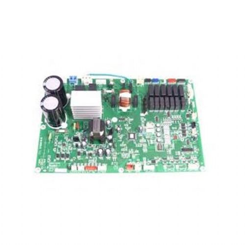
Lg Air Conditioning PCB Spare
Parts
|
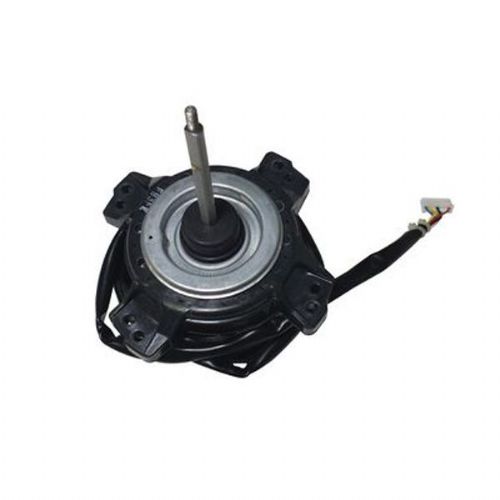
Lg Air Conditioning Fan Motors
And Blades
|
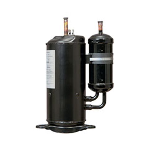
Lg Air Conditioning Compressor
|
Orion
air conditioning and refrigeration offer an UK installation,
service and maintenance on Industrial, commercial refrigeration and air
conditioning. Spare
parts supply on Bitzer, Copeland, Prescold, Carrier, Carlyle, Dorin,
Prescold, Frascold, Gram, Grasso, Hubbard, Maneurop, Trane and Sabroe.
Sales Installation and Service
UK: +44 (0)1234 841221
Tel UK: 01234 841221
Fax: +44 (0)1234 852662
Address:
Orion Air Conditioning And Refrigeration Limited
10 Grisedale Court
Woburn Road Industrial Estate
Kempston
Bedfordshire
MK42 7EE
United Kingdom
Email: [email protected]
|